home
| lewin's resume
| contact lewin
| larwe.com
capabilities
& pricing | projects | about
zws.com
|
home
| lewin's resume
| contact lewin
| larwe.com |
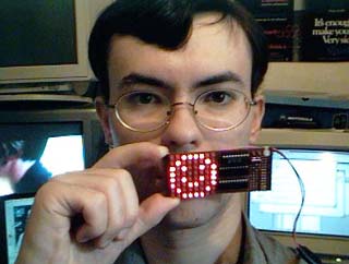
Picxie 2 - 8x8 Animated LED Signboard
Important: The firmware supplied in the current sourcecode archive is VERY BASIC. I do intend to draw more patterns. However, a vast workload coupled with possible emigration has put the finished firmware on hold. Please do go ahead and build this circuit though - the supplied firmware is fully functional. You can have hours of fun designing your own patterns and effects! Prototyping this simple circuit for my mother to use as a Christmas decoration has reminded me of several useful lessons, the most important of which is "trust the hardware!". You would not believe how many times I went over the wiring of this project looking for problems and subtle trickery, only to find that I had made a silly logical error in the firmware and that the hardware was in fact working perfectly. This illustrates the crucial importance of the First Law of Digital Circuit Design: Everything is a software problem. (This rule is rarely helpful in finding solutions in cases where hardware and software responsibility devolve on a single individual. However, it is always a good maxim to have in mind).
Before you look at this circuit diagram, NOTE WELL: Experience with all sorts of other published circuits tells me that I will receive a large number of questions asking if 74LS374, 74C374, 74S374, 74F374, 74ALS374, 74HCTLS374, etc. can be used in place of the 74HC374s specified. The answer to this question is that when I was designing this circuit, I had the datasheet for the Motorola 74HC374 in front of me. The circuit is designed around the source/sink capabilities, timing characteristics and acceptable supply voltage range of the 74HC374, and if you use anything else the result is not guaranteeable. At best you will see reduced battery life. With that warning out of the way, click the thumbnail below to view a full-sized image of the circuit schematic. It's really a very simple circuit, just fiddly to build (and to draw!).
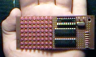
When you power up the device, it will briefly show the firmware version number onscreen, then it will plunge into the main animation loop. If you have built the original Picxie, you will see a big contrast in the complexity of graphics which can be shown on the larger screen of the Picxie 2. Although the basic design of this product is similar to that of the old Picxie, the details of how the display is generated are quite different. Because the PIC16F84 doesn't have enough I/O lines to drive all the LEDs directly, lines RB0-RB7 are used as a data bus connected to the inputs (D0-D7) of two octal flip-flops. The outputs of these flip-flops drive the row and column lines. RA0 and RA1 are used to clock data into the row/column lines. The way is paved here for all sorts of silly mistakes in writing the firmware - luckily for you I've already made all these mistakes and corrected them (read the comments in the sourcecode) so you should have no problems with crosstalk if you stick to my basic code. With an 8x8 display, the memory limitations of the 16F84 also become apparent. Working in this space reminds me most fondly of the Sinclair ZX81, a marvelous little Z-80 based micro. Your prototype could look something like the picture below. You will observe that I used 3mm round LEDs spaced as closely as possible on a piece of Veroboard, and that I put all the ICs very close together - plus, I only socketed the PIC, not the other ICs. This looks good and keeps the project nice and compact, but it presents some challenges - getting all the LEDs lined up perfectly, and installing the numerous small snippets of wire on the back of the board are the two major contenders. If you are unsure of your soldering skills, I suggest you use 5mm LEDs and space everything a little further apart. My technique for getting the LEDs straight is to "tack" solder one leg only, then adjust the height and rock the LED into position sighting along the rows and columns of already-installed LEDs before soldering the other leg. Misaligned LEDs will stand out very obviously while the circuit is running.
|