home
| lewin's resume
| contact lewin
| larwe.com
capabilities
& pricing | projects | about
zws.com
|
home
| lewin's resume
| contact lewin
| larwe.com |
Picxie - Animated LED SignboardThis holiday season, I was asked by a colleague to build him a LED flasher for a Christmas card he is giving his significant other. As usual, I got a little carried away with this project :-) The result is a "Saturday arvo project" circuit which may be of interest to beginner hobbyists keen to experiment with the popular PIC16C84/16F84 microcontroller. Briefly, it's a 4x4 pixel animated LED billboard of the type commonly seen at railway stations, in store windows and so on - only much smaller, of course. UPDATE: 04-Jan-99 - The 8x8 Picxie 2 is now available! UPDATE: 03-Dec-98 - Some more patterns have been added to the firmware for this product, which has been updated to V1.01.
The circuit, illustrated below, is so simple that it needs little explanation:
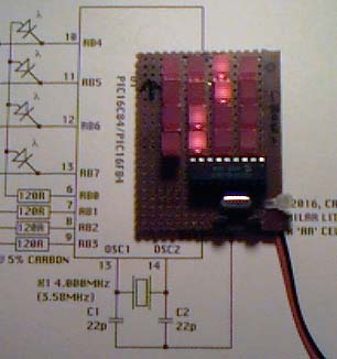
To drive the display, the PIC brings one of the row select lines (RB4 thru RB7) low, and places the data for that row on the column lines, RB0 thru RB3. This configuration is held for a short interval, then the next row is selected and the new data is placed on the column lines, and so on. A variety of patterns are programmed into the sample firmware, including a "comet" racing around the edge of the screen, a rotating propeller, twinkling stars, and a firework which spirals in to the center of the screen and explodes. What you display onscreen is limited only by your imagination... and the fact that with 16 LEDs, there are only 65,536 possible "pictures" :-) When you power up the device, it will run a quick test to prove that all wiring is correct - first, all LEDs will come on for a moment, then a black spot will walk along the screen from left to right, going down a line each time it reaches the rightmost edge of the display, until the bottom right corner is reached. This process is then repeated with a lighted dot on a black background, and then after a short pause on a blank screen, the main animation loop will start. Note: There are five unused I/O lines which could be used to expand the device to a 9x4, 8x5 or 7x6 pixel display with no extra external logic. The reason I left it at 4x4 was mainly because it's an easy number to work with, and makes it possible to store longer animations (since each frame requires less memory to store). Experiment, expand and comment! With two additional 8-bit latch ICs, you could make an 8x8 display, and with four of these latches you could build a 16x16 display which will allow you to create some quite complex animations; it's a LOT of wiring on those 256 LEDs, though! My mother wants a version that can display a rotating snowflake for Christmas, so possibly you will see a large-screen version documented here in the future. Email me if you would like to see some modifications made. Your prototype could look something like the picture below. Note that I used square LEDs. It's of no importance to the circuit, but if you use fairly tall square LEDs, the difficult task of lining them all up is slightly easier - poke them all through the board, flip the whole thing upside down onto a flat surface, and solder down all the legs.
|